Surveying on Surrey Hills Part 2 – From Chain to GPS

Technological Developments that changed surveying

In the first blog, we discussed the labour-intensive and time-consuming aspects of surveying. In this second part, we will look at the changes that occurred as a result of technology and how they made surveying a completely different vocation, and how these developments led to some major civil projects undertaken by the Roading & Survey Team at AFH/NFP.

Around the mid 80’s, computers and electronics were becoming more accessible. Things weren’t cheap, but as they were more affordable, we began considering how they could improve the what we did. This was not only in surveying but in all aspects of the AFH business.

Before we look at this, I thought it would be appropriate to go through where we were in the mid 1980s from a surveying perspective.

Wild T16 Theodolite Photo courtesy of Leica (Wild-Heerbrugg)

Firstly, the key instrument of our trade was the theodolite, as described in the first blog. Our original theodolite was a very heavy instrument and complex to operate and use.

I remember Bruce Hodgetts putting together a Capital Expenditure Application, CAPEX, for a new Wild T16 theodolite for around $10,000 plus extras for tripods and other equipment. It was a very detailed document focusing on efficiency and productivity gains, which were key to justifying the expenditure. It wasn’t a straightforward process, with several rewrites and iterations, before it was finally approved. When it was approved, Bruce drove down to Walsh Optics in Hobart to personally pick it up.

Whilst this was a great step forward, we still had to physically record the readings and use the survey staff and chain.

The next significant development in technology that was a quantum change in the way surveying was done was the Electronic Distance Measuring (EDM) equipment. Basically, this was an instrument that sent a light beam out to a reflector target and, from this, could calculate the slope distance from the instrument to the target.

Some of the early EDMs were very bulky and cumbersome. The first time I encountered this equipment was working with local survey firm Peacock, Darcy & Anderson (PDA) when we were doing the subdivision of some of the button grass plain country in the Woolnorth block along the West Montagu to Marrawah sand track, now the Harcus River Road. The picture below gives some context to the bulkiness of this equipment and it was only capable of measuring distances, so you still needed a theodolite as well to measure the bearing and slope.

Thankfully, the technological improvements were exponential in size, design and accuracy. We started looking at what EDMs were in the market in the late 1980s and having not long purchased the T16 theodolite compatibility with that was paramount. The manufacturer of the T16 also made EDMs that could be mounted onto the telescope of the theodolite, making them the precursor to what was to become known as the “Total Station”.

Once again, the process was for a Capex to be raised to purchase a Wild DI14 Distomat, two single reflector prisms, targets, prism poles and a tri-bac for mounting onto a tripod. Again, the approval process was quite convoluted, as being principally a forestry company, this type of equipment was poorly understood by those reviewing and ultimately approving. The equipment was finally approved thanks to Bruce’s patience, doggedness and salesperson skills.

HP 3800B EDM similar to the instrument used by PDA Photo courtesy of Hewlett Packard
WildT2 Theodolite fitted with DI14 Distomat Photo courtesy of Leica (Wild-Heerbrugg)

The photo left shows how the DI14 Distomat was mounted onto the telescope of the theodolite making the surveying tasks of bearing, slope and distance all being done from a single piece of equipment, but still had to be manually recorded.

Whilst technological developments of surveying equipment greatly changed the way survey fieldwork was being done, the most significant development was in computing.

I can vividly remember the first desktop computer that was purchased for the forest management area. It was a 20Mb dos machine. Yes, with the flashing green cursor! You had to type in dos commands to make it work and data was stored on 5 1/2”  floppy discs. I can still picture Andy Warner sitting at the keyboard typing in commands to enter CFI data and then produce summaries of the information.

All basic by today’s standards but at the time this was cutting edge and gave us a glimpse of what the future may hold.

We will now take another quantum leap on the surveying front. As already explained up until now despite the improvements in technology all measurement had to be manually recorded in field books and then the necessary computations had to then be done with handheld scientific calculators and then manually plotted and drawn. Now the calculators had become programmable which meant that the reduction of field measurements could be done quickly once the formulae had been programmed into the calculator, but there was still the requirement to write down the corrected measurements and then they had to be manually plotted.

The obvious next step was for the technology both in instruments and computers to record the field measurements and then reduce and plot the measurements on a computer. Enter the Total Station and Surveying Software.

We traded in the T16 and DI14 Distomat for a Leica TC1600 Total Station and purchased Geocomp Survey & Civil Engineering software.

Along with these purchases the Roading & Survey Team purchased a new IBM computer that was able to run Geocomp. Our “brothers” in the Forest Management Team had also seen the advantages new technology was bringing and purchased a HP A0 plotter. Now with all this technology we could do everything from field to processed data without having to write it down and then plot out the finished surveys, drawings and plans.

The last piece of technology that created a major impact on the surveying and forest management team, was the Global Position System. Back when we first acquired Global Position System equipment, the limiting factor was the availability of satellites. A minimum of three satellites were required to get a reasonably accurate location to within +/- 5 metres without being corrected. I can remember doing some control network surveys on Surrey, Woolworth and other freehold properties between 6:00 pm and 6:00 am, just because the satellites were only accessible during that period.

Leica TC1600 Total Station Photo courtesy of Leica (Wild-Heerbrugg).
Wild(Leica) GPS 200 Control Network Surrey Hills.
Andy Warner & Paul Nicholls consulting the User’s Manual for the Trimble GPS (always a worry with a forester and a User Manual!).

Major Civil Engineering Projects

I was very fortunate in my time as a surveyor with AFH & NFP, to be able to work on some very exiting civil engineering projects. Without the support of everyone involved and the advances in technology then these projects would not have been achievable.

I will talk about three projects that stand out for me in demonstrating what the people at AFH & NFP could achieve.

Hellyer Mine Rail Spur

Hellyer Rail Spur Alignment. Source Google Earth.

This project for me was one of the most satisfying achievements in my time working on Surrey Hills. I along with Bruce Hodgetts, Ken Gillard, Morris Bloom, Tim Price, and Ken Blackwell (EBR) were the project team. We were involved right from conception to commissioning.

The 11.5km of railway line was located, cleared, surveyed, designed, and constructed in 1989 by this team along with some very experienced employees and local contractors.

You might ask how a forestry company even got involved in building a railway line? Well at the time Pasminco, who owned the Emu Bay Railway (EBR) was owned by North Broken Hill (NBH) who in turn owned NFP. So NFP was asked to do the project as an internal company and because of the in-house expertise that we had.

This project was like building a road except that there were design limitations regarding maximum grades and curve radii.

I can remember sitting in the Burnie office with Bruce and Morris drawing alignments on 1:25,000 Tasmaps and then taking the “best” desktop alignment out into the field and locating using a compass and hip-chain. Needless to say, it took several attempts and realignments on the ground to come up with what we thought was a reasonable alignment. Between, Morris, Bruce, Ken G, Tim and myself I think we walked the alignment at least 9 to 10 times.

Once we had established a line in the field then we had to work with Ken B who was the EBR surveyor and designer. Ken was also a practising land surveyor whose survey plans Bruce and I had followed in relocating several of AFH/NFP’s property boundaries. Ken’s knowledge, expertise and guidance was invaluable in establishing the final design.

Harvested and partially cleared construction corridor. Photo courtesy of Morris Bloom.

The next stage was for harvesting contractors to come in and salvage what commercial timber was recoverable along the alignment and then clear to corridor with NFP plantation and roading dozer operators.

As the 40m corridor was cleared the surveying of the corridor commenced. This required establishing a survey control network and from this undertaking a detail survey of the entire 46ha (11.5kmx40m) alignment. This was undertaken with two survey teams, one under Tim Price’s guidance and me looking after the other team.  The survey took around 4-5 weeks to complete as we had to wait until areas were completely cleared. Thankfully we had access to the Leica TC1600 total station that measured and recorded all the data.

Once the detail survey was completed then the data was imported into the Geocomp software where it was edited and processed to develop a Digital Terrain Model (DTM). From this then the horizontal and vertical alignments were designed and reviewed. There were several key constraints to the design, one being the 2% grade the others being physical such as the take off point on the existing EBR line, the crossing of Moory Road, Hatfield River, Romney Marsh, Belvoir Road and the loading point at the Hellyer mine. Because of these constraints there were several iterations of the vertical alignment to ensure the design levels at the key crossing points were achieved. The other physical consideration was the geology along the alignment with columnar basalt underlying less than 1m of topsoil in the areas off Racecourse Road and through Murrays Plains and trying to minimise the depth of the cuts particularly through these areas of basalt. Ultimately some cuts were not avoidable and there were some areas there were over 10m deep cuts.

Bruce, Morris, and drilling contractor along with some of the equipment used in the construction through the columnar basalt regions. Photo courtesy of Morris Bloom.

Once the clearing and final design was completed then the construction set out began, locating batter pegs at every 10m along both sides of the alignment. This meant that we had to locate 2,300 batter pegs! These provided the guide for the construction work to be undertaken, but more often than not I think they were a target for the construction crews, as we were constantly reinstating them.

The construction plan was to have the construction split into two sections. Section 1, managed by Morris was from the EBR take off point to Racecourse Road and Section 2, managed by Ken G was from Racecourse Road to the Hellyer Mine loading point. We had a survey crew assigned to each section one managed by Tim and the other by me.

Initially the setting out was straight forward in that we started from a given point and worked south or north along the alignment, but as construction got underway, we soon found out that there were several areas being worked at the same time. This meant we had to be at several different places throughout the day establishing batter pegs, checking levels, and relocating disturbed pegs.

A “Surrey” Winter. Photo courtesy of Morris Bloom.

Now, anyone who has worked on Surrey Hills, particularly south Surrey knows that the weather can be unpredictable even in the middle of summer, but the winter is a very challenging time to be outside doing survey work. The construction phase of the project took only six months but some of this was undertaken in the winter months as you can see from the photos above and the one left.

Not very nice conditions for anyone to work in! It was testament to everyone who worked on this project to complete the construction in those six months, when initially it was planned to be constructed over two summer periods.

As with any project there were plenty of challenges, such as when we found that a section of the alignment through Romney Marsh followed a watercourse which meant that when the excavation was done then the watercourse would flow down the alignment. This meant that I had to do a redesign of this section, which was done overnight and the new alignment and set out details were ready for work the next morning.

The large amount of basalt that had to be moved proved very useful as it was used for base on access tracks as well as being screened and then used as the base ballast for the rail line. This was a significant benefit to the overall cost of the project and meant that with this rock the access tracks could be used during the winter, significantly reducing the project timeline.

I would be remiss of me not to recognise everyone involved in this project. Most of the time everyone worked well together, however there were the odd occasions where demands for equipment, drilling crews and surveyors tested the patience of everyone. One incident I remember was that we found that the TC1600 instrument that we had hired was faulty and meant that the measurements on batter pegs set out using this instrument were incorrect. Thankfully we picked up the error before final levels had been achieved and that wasn’t in the basalt cuts!  But it did mean that rework of the cuts and fills affected had to be be done, much to the chagrin of Morris & Ken G.

It is interesting now when reflecting on this project how involved everyone was. There was a single focus of getting the job done, which was sometimes all consuming. But to achieve what we did was amazing, given that none of us had been involved in a project of this sort before. It also demonstrated what great skills the people of AFH/NFP possessed and their ability to tackle projects that were challenging.

I think this project gave everyone involved the confidence to take on other civil projects, such as the Hampshire Chipmill, Somerset Nursery, Wesley Vale Pulp Mill and major road projects such as Massey Greene Truck Route and Boco Road. I was fortunate to be involved in all these projects along with Bruce and Morris, which I know forged lifelong friendships.

I have included a couple of plans and photos from some of these projects so you can get an appreciation of what was achieved, as well as some more from the Hellyer Rails Spur.

Thanks to Bruce and Morris for providing photos, guidance, and recollections, but most of all  for their support and friendship. A great time in my working life and something I will never forget.

Basalt used as base for rail line formation. Photos courtesy Morris Bloom.

Belvoir Road Underpass (Bebo Arch) construction. Photo courtesy Morris Bloom.

Track being laid by EBR and finished track (Note the “good weather”!). Photos courtesy of Morris Bloom.

Hellyer Rail Spur Looking north (left) and south (right) from Belvoir Road.

The Hampshire Chipmill Project (HCMP)

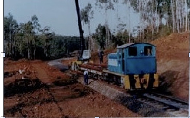
The HCMP was another civil earthwork project undertaken by the NFP Survey & Roading team.

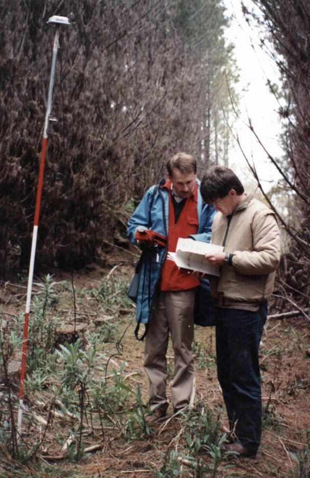
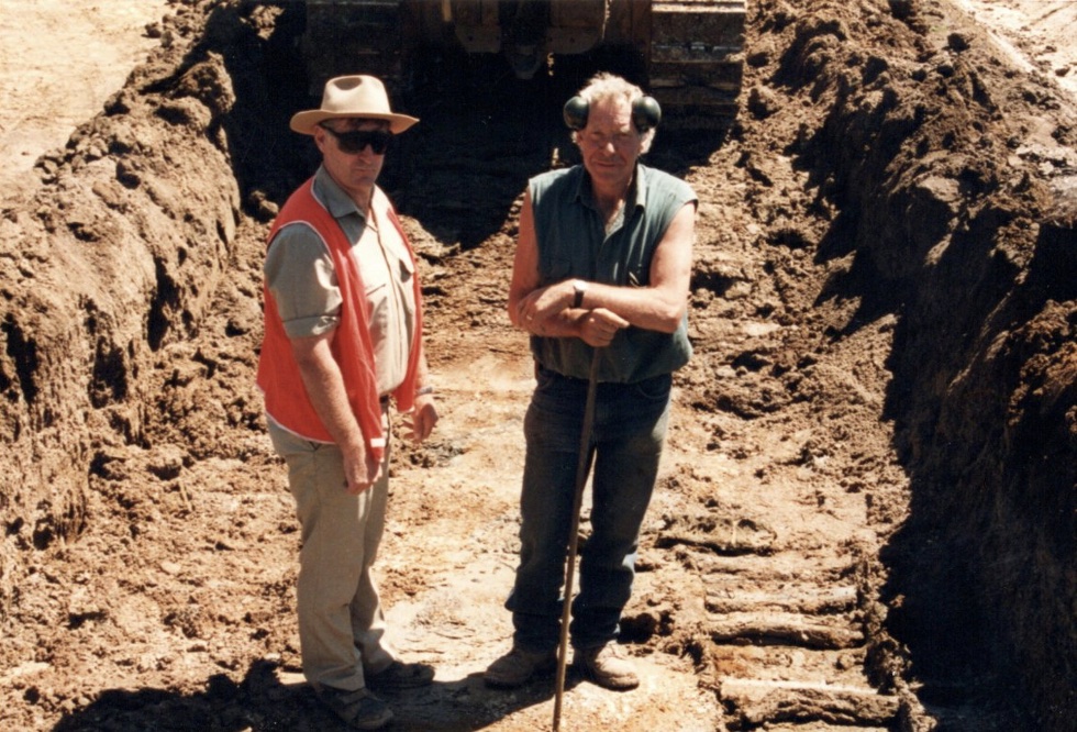
The Team consisted of Morris Bloom, looking after the earthworks and myself, assisted by George Malley, doing the earthwork’s design and construction set out.

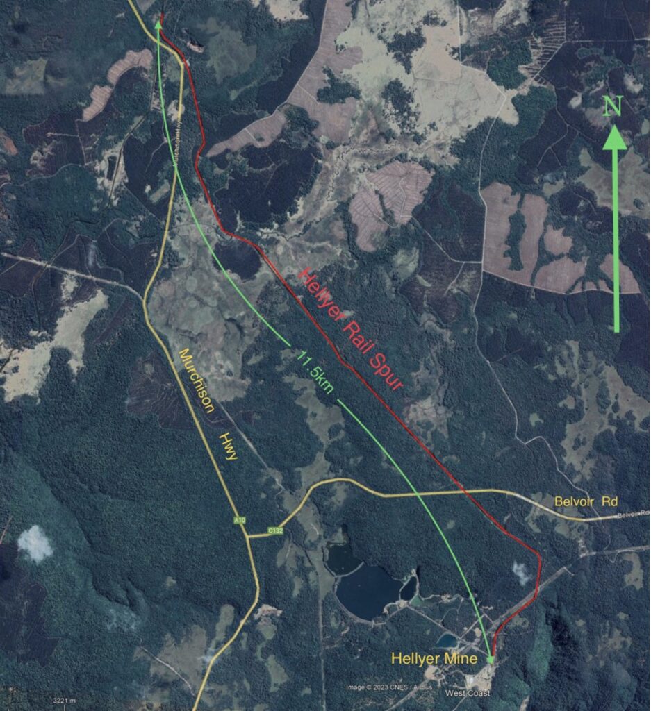
Unlike the Hellyer Rail Spur project, we used aerial photography provided by Hydro Tasmania to produce a Digital Terrain Model (DTM) of the site. This DTM was proven to have a horizontal and vertical accuracy of >50mm which was certainly adequate for the earthwork’s construction.

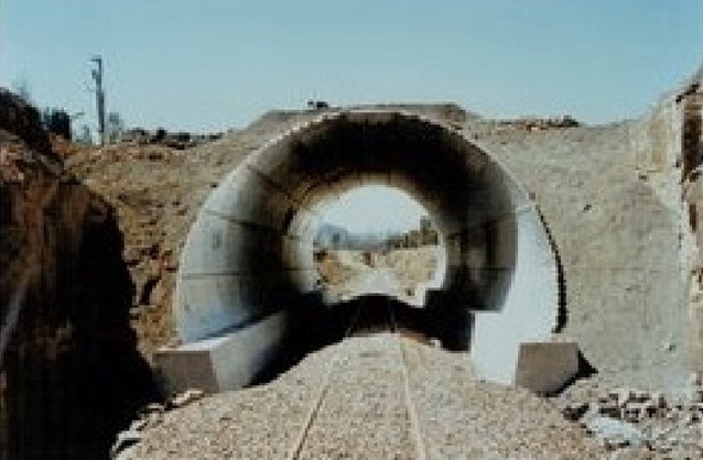
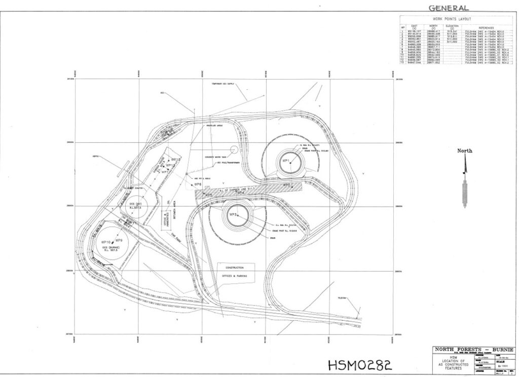
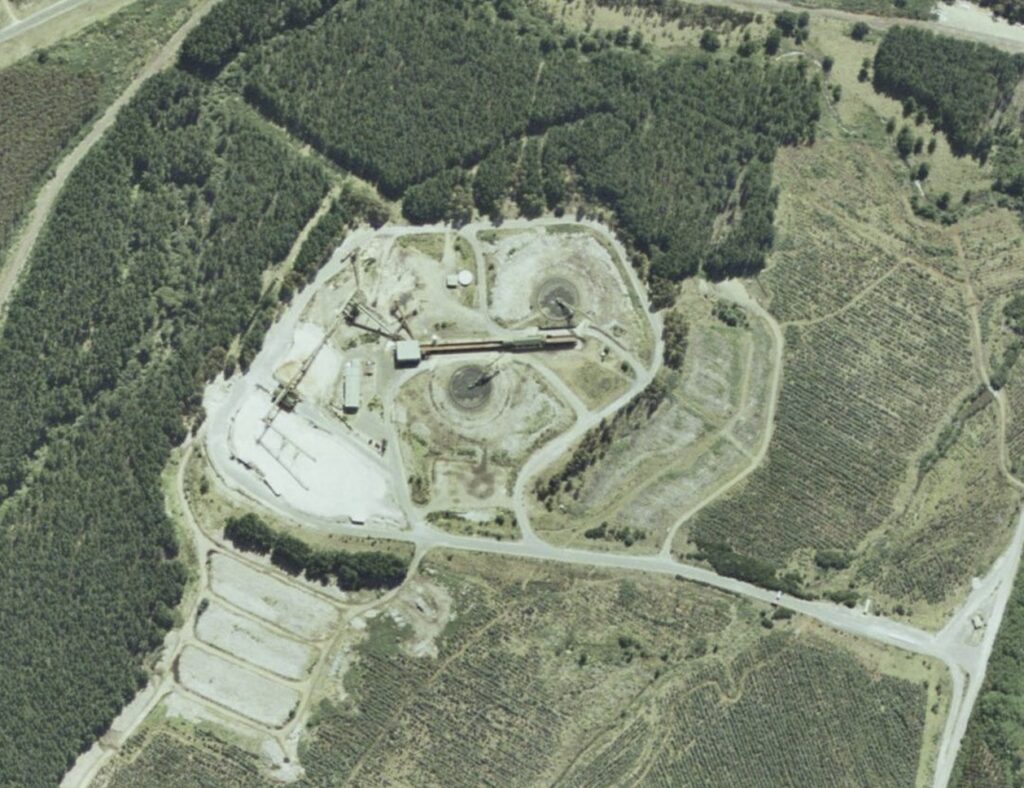
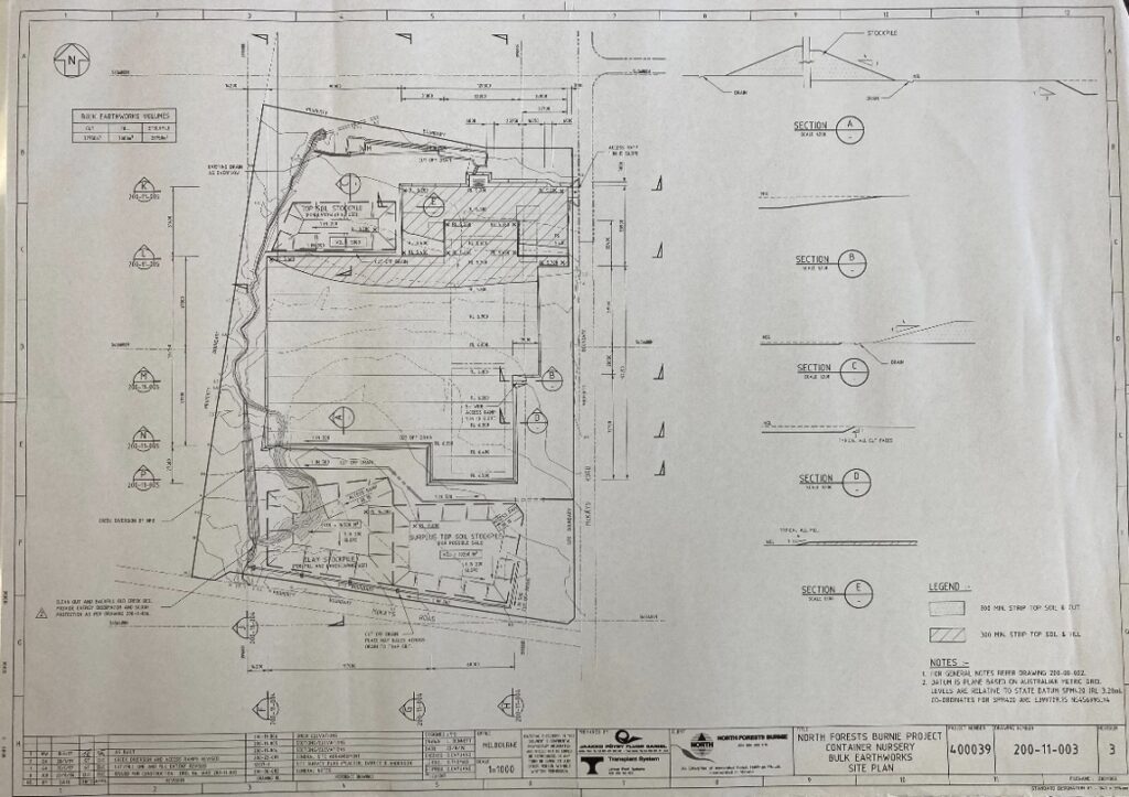
The earthwork’s design comprised all the road access as well as the base for the actual mill and associated infrastructure, such as the radial cranes, chip stockpiles, conveyors, infeed line, chipper building, and office.

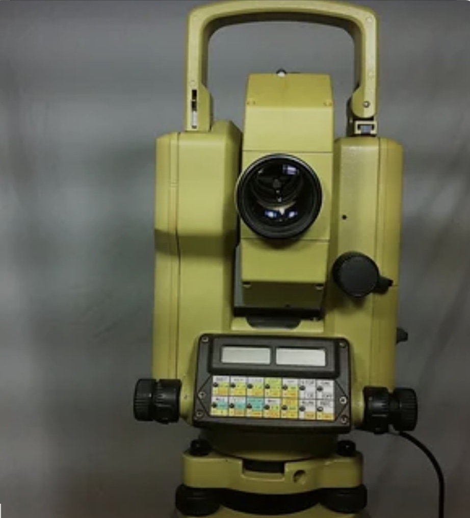
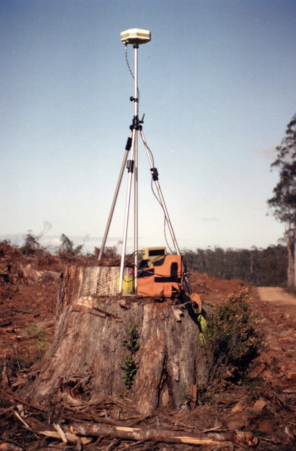
By this stage, 1994, we had access to high accuracy GPS so that control points for the photogrammetry and set out were coordinated using this technology and then further refined using the TC1600 theodolite to undertake the final survey of the control stations around the construction site. With the higher tolerances required for the finished surfaces, more rigorous horizontal and vertical control was undertaken with the whole control network, then adjusted using the least squares methodology resulting in an accuracy of >10mm across the network.

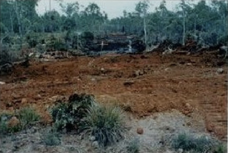
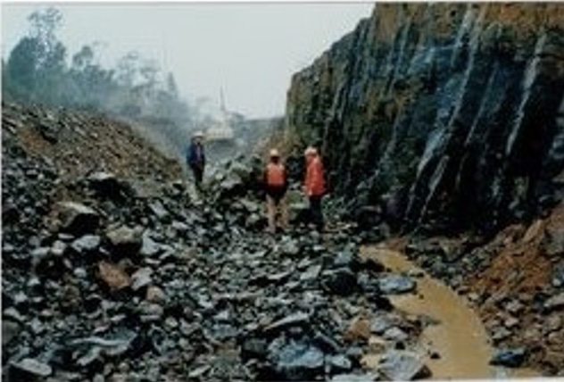
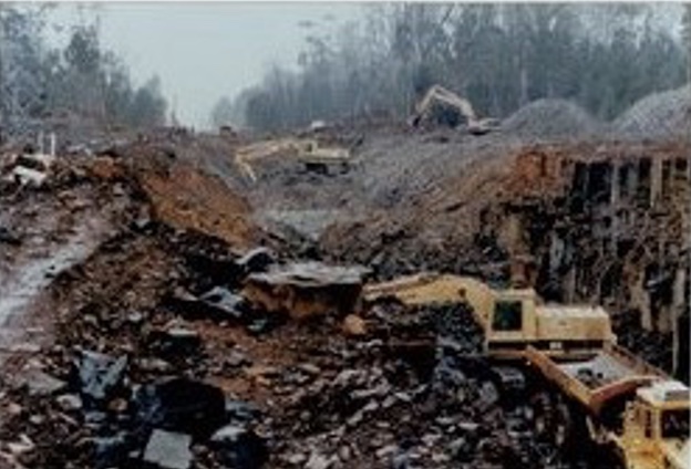
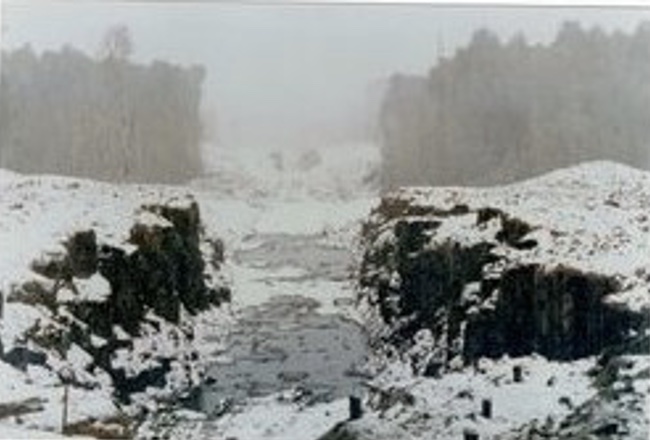
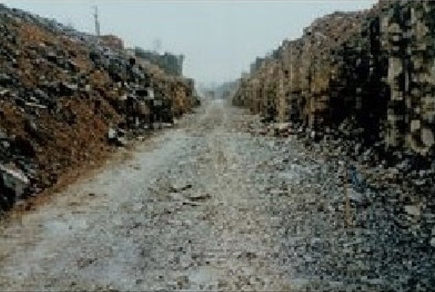
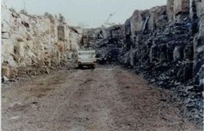
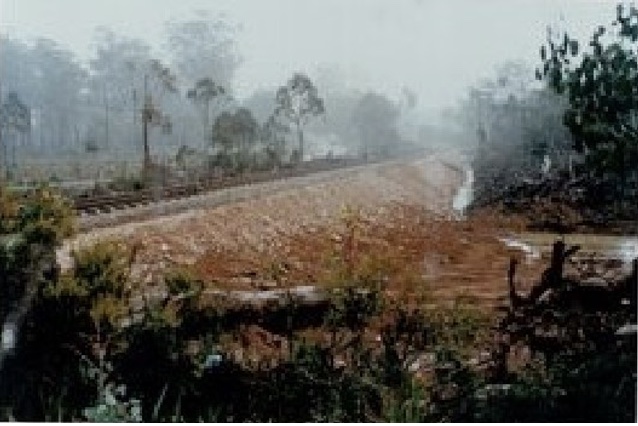
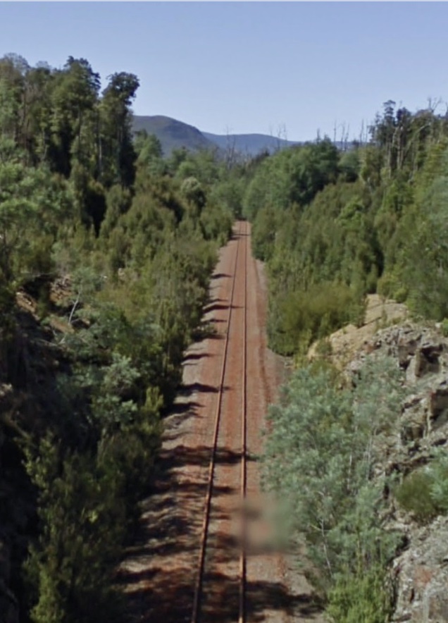
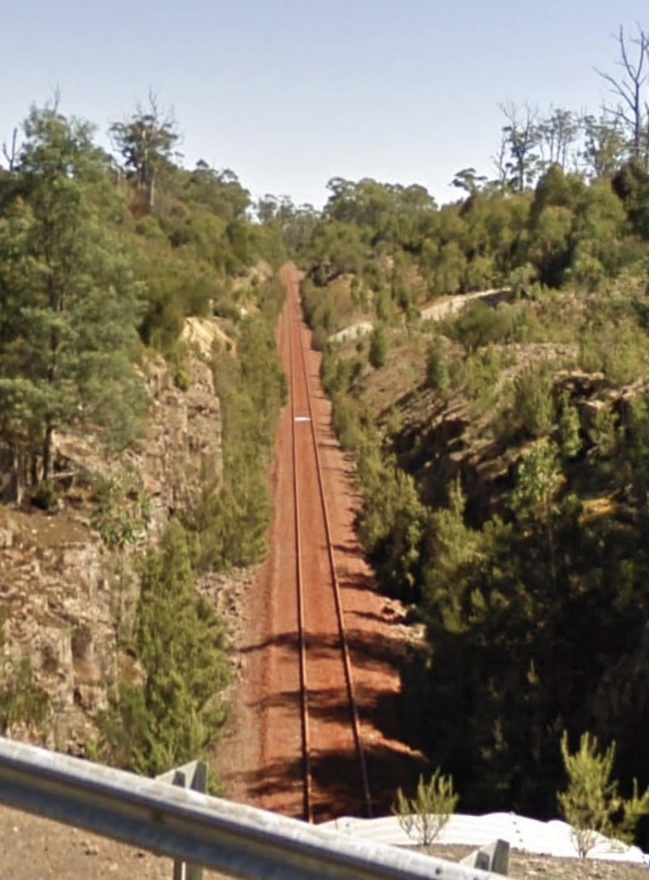
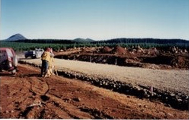
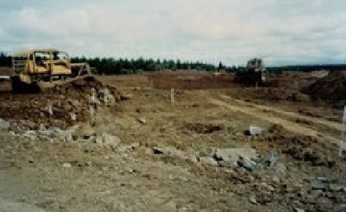
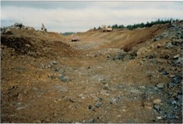
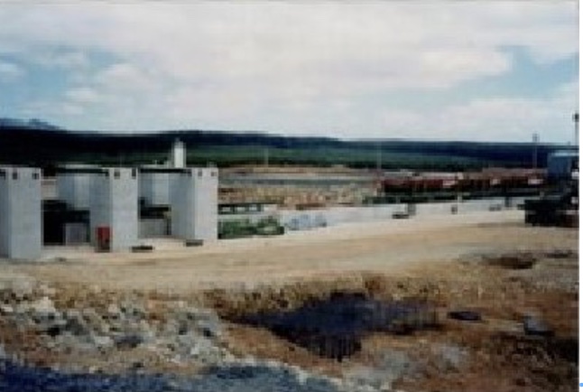
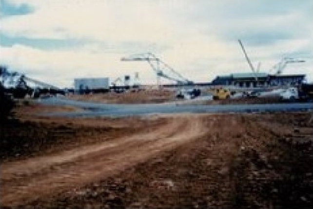
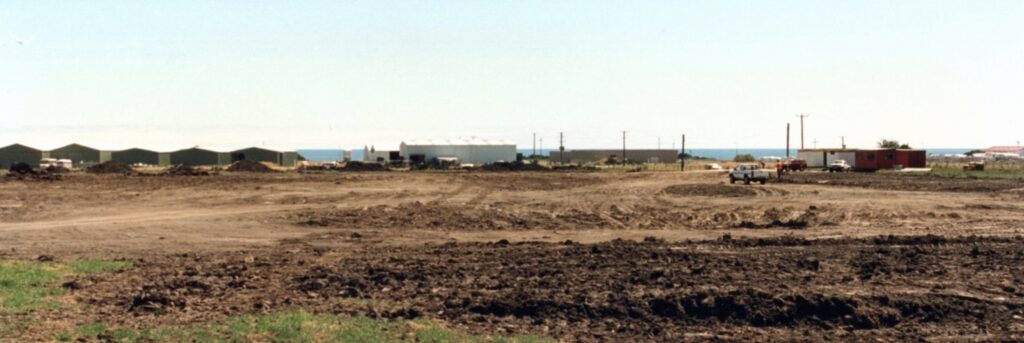
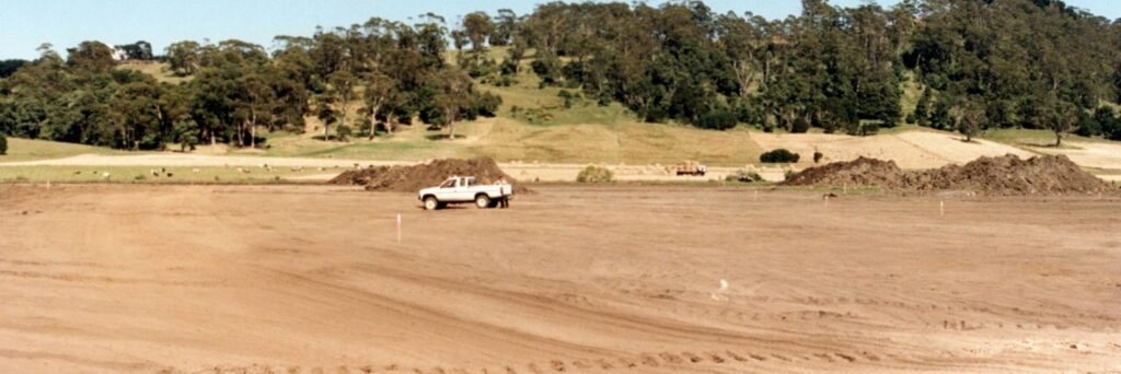
As you can see from the photos, whilst the site was relatively flat, there was still quite a bit of material to be moved. A key part of the design was ensuring the cuts and fills balance to minimise the movement of material offsite. The other design consideration was the flow and interaction of traffic onto and off the site, with daily operations having a mix of log truck deliveries and chip truck loading. The design also called for the roads to be bitumen sealed, so final construction levels had to be measured to a tolerance of >25mm.

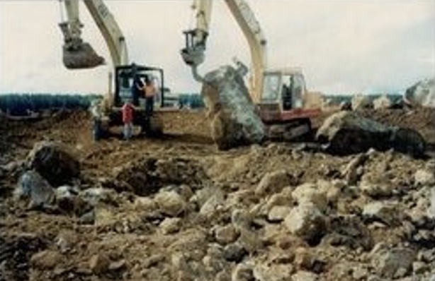
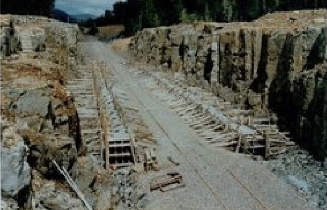
No matter where you are on Surrey Hills, you can always guarantee that you will find rock; this site was no different. Some of the big “floaters” or “goolies” were used in constructing rock retaining walls or protection barriers for infrastructure, again using the resources available.

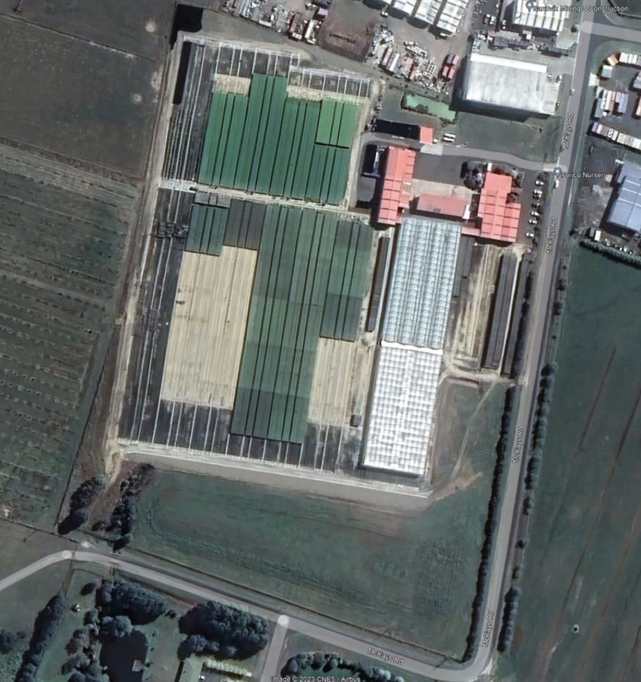
Thanks again to the NFP team. The section of the project we were responsible for was completed on time and within budget and provided to base platform for the chip mill infrastructure to be installed.

As Constructed Survey Plan done by the writer.
Aerial Photograph of Hamshire Chipmill, circa 2006.
The writer with the trusty TC1600 setting out. Photo courtesy Morris Bloom.
Some of the basalt “goolies” onsite. Photo courtesy Morris Bloom.

Civil earthworks works. Photos courtesy Morris Bloom.

Mill under construction. Photos courtesy of Morris Bloom.

Somerset Nursery

It appeared by the mid-1990s the Survey and Roading Team of NFP had become recognised for their ability and expertise in undertaking civil earthwork construction projects, so when the development of the Somerset Nursery was approved once again, Morris and myself were seconded into doing the earthworks design and construction.

This project had its challenges, primarily because the soil on the site was clay, and it was between 5m to 10m above sea level.

This meant that you didn’t have to dig down too far and encounter moisture which in clay is fine until the moisture percentage changes, which causes the clay to shrink or expand.

Once the topsoil was removed then, the quantum of this became apparent. To maintain a constant moisture percentage in the clay, the finished site had to be well compacted and sealed.

Again, the project was completed successfully to requirements, and the site is still operational today.

Site Plan Somerset Nursery.
Aerial Image Somerset Nursery circa 2023. Image Google Eart.
Morris and Leo Butler on-site during construction of the nursery. Photo courtesy Morris Bloom.

6 thoughts on “Surveying on Surrey Hills Part 2 – From Chain to GPS”

  1. Herbert Illichmann

    Hellyer spur line – that takes me back quite a number of years. Thanks for writing it up.

  2. Another great blog Robert. So much interesting information including all the technical equipment involved . So good to hear the names of several of the colleagues Ross often talked about. I had no idea about all the development that occurred in Surrey Hills. The earth works involved and the railway development. Such as achievement by a wonderful team of experts.

  3. Robert MacAulay

    Great write up. I may have to let the cat out of the bag though guys. After one of your GPS control points was placed on Guildford Rd for a couple of days, the truckies thought it was of my doing and slowed down accordingly. I never either admitted nor denied it. Great safety device.

    Ken Gillard was assigned as my minder when I joined Tasmanian operations in ’89. I learnt a lot from him and all those mentioned in your story. I am a better person for having the opportunity to have worked with you all.

    Thank you.

  4. Brings back a lot of memories Mike.

    I remember at least 16 machines to keep active and productive. With machine operators and others required we had about 35 personnel working in that time.

    I learned so much on this project, we did have a great team and work ethic.

Leave a Comment

Your email address will not be published. Required fields are marked *